In the sprawling complexes of piping, distillation columns, and tanks that constitute oil and gas refineries, precision is not just a matter of efficiency—it’s a prerequisite for safety, compliance, and technological advancement. As such, Computer-Aided Design (CAD) has become an indispensable tool in the design, operation, and maintenance of Oil and Gas Refineries. Digitise IT has emerged as a leader in delivering high-quality CAD drafting solutions for the oil and gas industry, catering to the needs of refineries worldwide with a combination of 23+ years of expertise, innovation, and meticulous attention to detail.
Orthographic Piping Diagrams
Orthographic drawings, also known as plans and elevations, are a series of flat two-dimensional views of an object. An orthographic piping diagram will typically consist of the top view (plan), front view (elevation), and side view (profile). Each view is projected perpendicular to a corresponding plane of projection, which means there is no distortion or perspective. The critical characteristics of orthographic diagrams are as follows:
- True Scale Representation: Orthographic projections display the true size and shape of the components as they would appear if looking straight on at one face of the object.
- Multiple Views Needed: Since orthographic projections are 2D, multiple views are required to represent all features of a three-dimensional object.
- Dimensional Accuracy: These diagrams are used to accurately convey dimensions and layout information necessary for construction and fabrication.
- Clarity in Details: Because there is no foreshortening or perspective, detailed features such as exact placement of bolts, welding spots, and other intricate components are clearly defined.
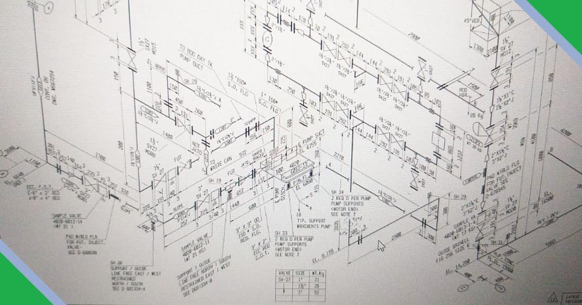
Isometric Piping Diagrams
Isometric diagrams, on the other hand, provide a different approach. These drawings simulate a three-dimensional view of an object, with the primary characteristic being that the vertical lines are drawn vertically, and the horizontal lines are drawn at 30 degrees to the base line. The distinguishing features of isometric piping diagrams include:
- Pseudo-3D Representation: Isometric drawings represent a three-dimensional object on a two-dimensional surface but are not in true perspective, as the scale along each axis is the same.
- Single View Sufficiency: One isometric diagram can capture all visible sides of the object, giving a more immediate understanding of the object’s overall form.
- Non-Distorted Measurements: While the isometric view appears distorted, measurements along any axis are true to scale, which allows for easier dimensioning and scaling directly from the drawing.
- Enhanced Spatial Understanding: These diagrams are particularly useful for visualizing complex interweaving piping systems and for conceptual purposes where spatial comprehension is vital.
Comparative Analysis
While orthographic drawings excel in precision and detail, they require a viewer to mentally compile multiple views to understand the entirety of a complex object. Isometric drawings simplify this by providing a more complete representation in a single image, which is particularly beneficial in piping to understand routing, supports, and relationships between components.
Application in Piping Diagrams
In piping diagrams specifically, orthographic views are essential during the detailed design phase, where exact specifications are needed for manufacturing and construction. They are also crucial for floor plans and elevation drawings in the layout of plant design.
Isometric piping diagrams, however, are invaluable during the conceptual phase, where understanding the interaction between systems is more important than the individual dimensions of components. They are often used for assembly drawings and for on-site contractors who need a visual reference to guide installation and maintenance without delving into the nitty-gritty details.
Conclusion
Both orthographic and isometric piping diagrams play integral roles in the visualization and construction of piping systems. Orthographic diagrams bring precision to the table, while isometric diagrams offer an immediate visual grasp of a complex object. In practice, the two are often used in tandem; isometric diagrams facilitate understanding and communication of the overall design, while orthographic projections provide the detail necessary for accurate fabrication and assembly. For engineers and draftsmen, mastering both forms of diagrammatic representation is essential to effectively bring a piping system from the drawing board to real-world implementation.