In large-scale infrastructure developments, what you can't see will almost always disrupt what you can see. Subsurface utilities, complex structural interfaces, and poorly coordinated utility networks represent the single largest risk vector for budget overruns and project delays. High-precision utility mapping services and advanced 3D infrastructure modeling provide the preventative framework engineering and construction giants rely on to uncover hidden conflicts before ground is ever broken.
The True Cost of Utility and Infrastructure Blindspots
For decades, construction projects have operated under a structural vulnerability: reliance on incomplete, legacy, or fragmented as-built documentation. When managing large site projects—such as industrial parks, master-planned townships, or transport corridors—the sheer density of buried assets creates an incredibly complex puzzle. Striking an unmapped electrical feeder, gas line, or wastewater conduit triggers a chain reaction of compounding liabilities.
Engineering surveys indicate that a significant majority of all construction change orders are caused by unforeseen site conditions, particularly undocumented or misaligned utilities. The consequences go far beyond the immediate repair invoice:
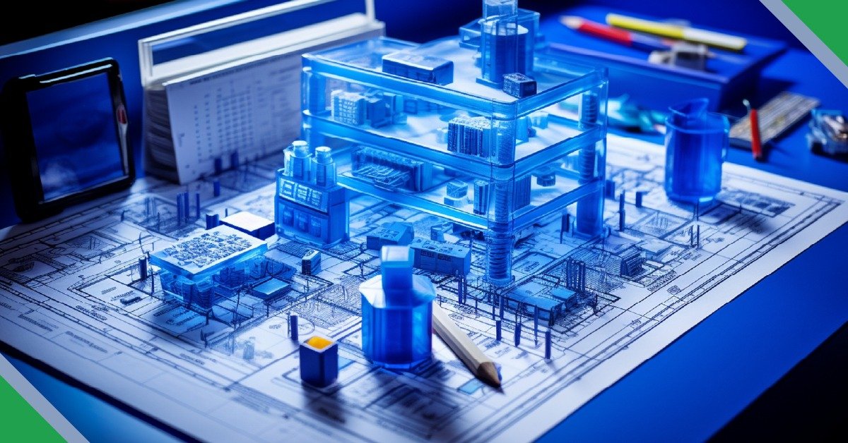
The cost of resolving a geometric clash or utility breach in the field is orders of magnitude more expensive than modifying a digital model during design. By moving away from static, compartmentalized 2D blueprints toward smart, multi-dimensional 3D utility modeling, engineering consultancies and main contractors convert these liabilities into highly predictable operational schedules.
How 3D Infrastructure Modeling Mitigates Construction Risks
Modern infrastructure design demands a paradigm shift from traditional isolation to dynamic integration. Infrastructure assets are no longer treated as independent lines drawn on separate sheets; instead, they exist as interactive objects within an intelligent spatial ecosystem. Let’s look at the primary mechanics through which rigorous modeling mitigates risk:
1. Automated Multi-Discipline Clash Detection
When civil structural plans, grading layouts, and deep utility networks (freshwater, stormwater, electrical conduits, and fiber optics) are designed in siloes, field interference is inevitable. By combining these independent data layers into a federated 3D model—utilizing tools like Autodesk Revit, Civil 3D, and Bentley MicroStation—specialist CAD operators run comprehensive clash detection routines. Navisworks and BIM-driven validation parameters instantly flag spatial interferences, such as a major storm drain intercepting a newly planned structural piling grid, allowing engineers to route conduits optimally long before mobilization.
2. Geospatial Context and Georeferencing
Isolated CAD drawings often lack real-world geographic references, posing unique hurdles when mapping assets across expansive geographic stretches. Integrating GIS utility mapping ensures every entity is tied precisely to absolute Earth coordinates (such as specific WGS84 or local State Plane projections). Alignment with real-world terrain contours, property boundaries, and adjacent infrastructure prevents misalignment errors that frequently occur when contractors translate abstract grid drawings to actual GPS points on-site.
3. Subsurface Utility Engineering (SUE) Visualizations
Following ASCE standard guidelines, utility tracking relies on varying Quality Levels (from Quality Level D based on historical archives to Quality Level A based on non-destructive vacuum excavation exposures). Advanced 3D modeling transforms raw attribute data from these SUE surveys into a complete volumetric map. Engineers can visually assess the depth, material limitations, soil buffers, and proximity clearances required around ultra-high-voltage lines or volatile high-pressure gas conduits.
The Workflow Breakdown: From Raw Field Data to Construction Assets
An effective infrastructure CAD drafting and modeling strategy requires a rigorous data transformation pipeline. Whether capturing historic campus developments or laying out a smart city corridor, data must be structured systematically to guarantee validity.
GIS & Mapping Ingestion
- Digitization of legacy paper schematics and asset registries
- Conversion of CAD polylines into attribute-rich GIS feature classes
- Topology validation to ensure network connectivity (no leaks or breaks)
- Integration of drone imagery and orthomosaics for context validation
- Population of database tables with material, diameter, and install year
Advanced 3D Modeling Outputs
- Creation of parametric 3D utility corridors (LOD 300/350 construction-ready)
- Extraction of highly detailed 2D structural detail and layout sheets
- Generation of exact material schedules and accurate quantity take-offs
- As-built model generation derived from point-cloud laser scanning datasets
- Federated master models tailored for downstream Facilities Management
The synchronization between GIS asset intelligence and 3D CAD accuracy yields a single source of truth. Field crews receive layout profiles that perfectly mirror the physical reality of the site, eliminating blind spots and costly guesswork.
Core Utility Networks Enhanced by Precise Modeling
Every utility network features unique geometric and technical constraints that demand domain-specific modeling knowledge. Generalist drafting often misses the engineering nuances that distinguish a functioning network from an unbuildable model.
Water & Wastewater Networks
Precision gravity-flow calculations require strict invert level tracking and gradient parameters. Modeling ensures correct pipe slopes, preventing pooling and compliance failures.
Power & Telecommunications
Managing overhead sag clearances and underground conduit bank bend radii. Proper 3D spacing separates high-voltage interference from sensitive telecom lines.
Gas & Fuel Pipelines
Strict safety buffer zones and clearance offsets around volatile pipelines. High-consequence area mapping integrated directly into spatial layouts.
Transportation & Drainage
Correlating roadway grading, cross-slopes, and structural retaining systems directly with catchment basins and under-road stormwater infrastructure culverts.
Strategic Execution: In-House Infrastructure CAD vs. Specialist Outsourcing
Maintaining a dedicated in-house team proficient across ArcGIS, Revit MEP, Civil 3D, and MicroStation presents significant financial and organizational hurdles for AEC companies. Infrastructure projects naturally experience cyclical demand spikes, meaning full-time overhead costs frequently drain corporate margins during transitional project phases.
By engaging a specialist offshore technical partner, global firms introduce highly flexible scale into their production engines. Senior engineers can focus exclusively on strategic conceptual planning, client management, and core engineering calculations, while an extended offshore delivery hub executes high-volume, precision drafting tasks.
- Significant Operational Cost Adjustments: Scale down resource overheads by up to 40% compared to maintaining internal software licenses and permanent specialized staff.
- On-Demand Capacity Scaling: Swiftly onboard complete production teams to hit strict multi-stage tender submissions or compliance delivery schedules.
- Rigorous Quality Assurance Standards: Specialized partners operate within strict verification frameworks, ensuring every delivery complies with customer-defined CAD metrics and global BIM/GIS specifications.
- Seamless Legacy System Conversions: Efficiently handle millions of linear meters of legacy records or complex point-cloud extractions without stalling current design pipelines.
DigitiseIT brings over 25 years of specialized expertise in delivering high-precision GIS utility mapping, 3D infrastructure modeling, and advanced CAD drafting services. Acting as an agile, elastic extension of your design office, we support global engineering leaders across the UK, North America, Europe, and Australia, ensuring error-free documentation and enhanced profitability. Consult with our engineering mapping experts today →
Protect Your Next Infrastructure Project From Costly Errors
Get in touch with our team to share your spatial documentation goals, and we will formulate a precise execution plan optimized for your timeline and budget.
Initiate Project DiscussionFrequently Asked Questions
CAD files focus heavily on exact geometric layouts, structural dimensions, and construction-level drawing details. GIS datasets focus on broader spatial relationships, global coordinate georeferencing, and rich attribute profiles (such as component age, material specifications, operational status, and relational network topology). Integrating both allows a 3D CAD model to interact intelligently with regional utility infrastructure networks.
Scan-to-BIM involves deploying terrestrial laser scanners or drone-mounted LiDAR to capture millions of physical data points (point clouds) of an existing asset. Specialist CAD technicians then process these point clouds to accurately trace and reconstruct highly detailed, to-scale 3D models and structural drawings, uncovering hidden physical realities and updating unmapped asset logs.
Topology rules verify the mathematical and spatial continuity of utility lines. It programmatically ensures that pipes connect at junctions without accidental gaps, polylines don't self-intersect incorrectly, and directional flow logic remains mathematically valid. Without proper topology validation, hydraulic modeling and predictive network tracking become impossible.
Yes. Paper-to-CAD or raster-to-vector conversion is a core operational process. Source records undergo high-resolution scanning, structural georeferencing using reliable survey control parameters, and precise manual vector digitization to align older legacy footprints with modern design environments.